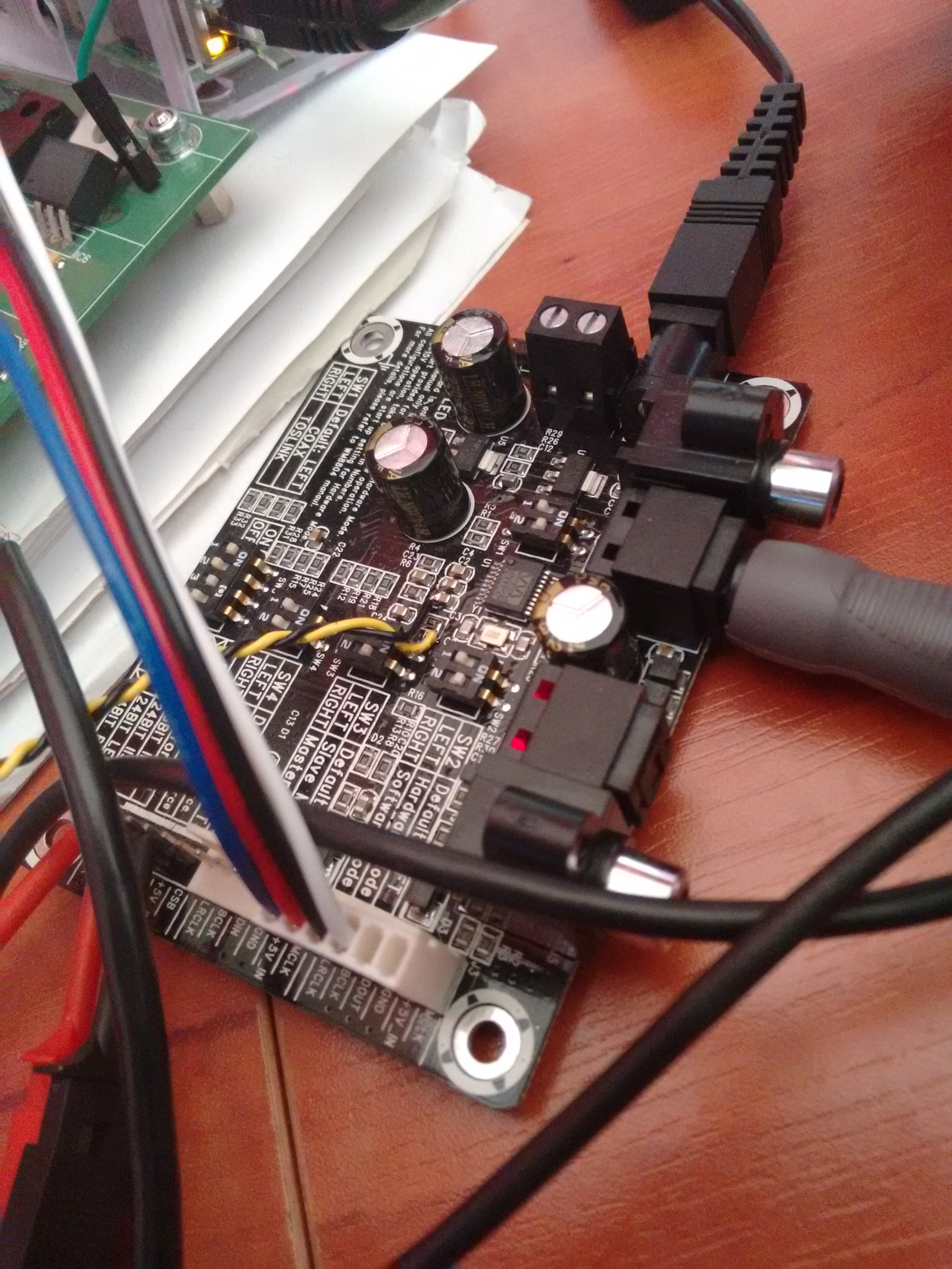
WM8804 application board (eBay) modified to output CLKOUT pin (yellow-black wire)
Recently I needed a special type of I2S signal, namely a 4 signal set of DATA, BCLK, FCLK and also an MCLK of 49.152 MHz.
Many modern DACs, DSPs and digital power amplifiers need this high clock frequency. And of course you would want this signal to be synchronous to the Frame Clock such that the converter has a fixed number of MCLK per FCLK cycles so as to minimize jitter.
Many S/PDIF receivers implement a fixed clocking in hardware mode which limits your options and flexibility, so it is worth exploring software control. It is really not so hard.
The use of an Arduino is perfect for a prototype. If I were to develop something for serial production using e.g. a PIC processor, I’d still build a first prototype with an Arduino – just to prove the concept quickly and get a feel for how much memory and features you need. When you have the control algorithm running, then you can then go and recode it on your target processor.
I chose to go the I2C route; SPI is available as well but I have a very simple PIC in mind as target processor so need to save on number of wires. For both SPI and I2C you will need the wire library in your code.
#include <Wire.h>Reading a status register over I2C
Starting out by reading a register makes the most sense, since the data sheet can tell you at least the content of the chip ID register, such that you can verify that your function is, erm, functioning correctly.
Reading a register is actually harder than writing to one. The trick is in the ‘repeated start condition’ and takes some searching to get right (also, older Arduino wire libraries don’t support it).
The WM8804 datasheet is pretty clear on what you have to do-
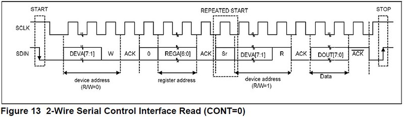
This is how I implemented it inside a function call:
byte ReadRegister(int devaddr, int regaddr){ // Read a data register value
 Wire.beginTransmission(devaddr);
 Wire.write(regaddr);
 Wire.endTransmission(false);  // don't send stop condition, keeping connection alive.
 Wire.requestFrom(devaddr, 1); // only one byte
 byte data = Wire.read();
 Wire.endTransmission(true);
 return data;
}
on the fourth line you see that the ‘repeated start condition’ is implemented in Arduino as an endTransmission with false as argument. Later on when the value has been read, the same endTransmission is called with true as argument which causes the Arduino to let the SDIN line driver go tri-state, and it is subsequently pulled up by the mandatory I2C pull-up resistors.
With the WM8804/WM8805, you can now verify your connection by reading registers 0/1/2:
Serial.print("Device ID: ");
 byte c = ReadRegister(wm8804, 1);
 if (c < 10) {
 Serial.print('0');
 }
 Serial.print(c,HEX);

 c = ReadRegister(wm8804, 0);
 if (c < 10) {
 Serial.print('0');
 }
 Serial.print(c,HEX);

 Serial.print(" Rev. ");
 c = ReadRegister(wm8804, 2);
 Serial.println(c,HEX);
when everything works, this gives
Device ID: 8805 Rev. 4
that’s right, a WM8804 IDs itself as 8805. That’s because it really is just a crippled 8805. Oh no they didn’t! Oh yes, they did. And so does everyone else. Deal with it.
Writing an I2C command
According to the data sheet, this is what you have to do:
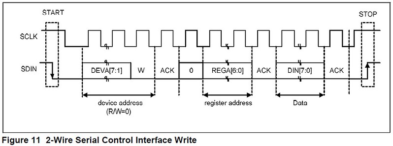
which translates as follows in Arduino
void WriteRegister(int devaddr, int regaddr, int dataval){ // Write a data register value
 Wire.beginTransmission(devaddr); // device
 Wire.write(regaddr); // register
 Wire.write(dataval); // data
 Wire.endTransmission(true);
}
as you can see, this is really much easier.
Constructing an application
Now that you can read and write registers, it makes sense to take a look at the status registers 11 – 17. Here, everything you control on the chip, as well as everything the chip does itself, is reflected.
Register 11 is the interrupt register. Whenever something has happened that changes the state of the chip, it is registered here. You can choose to make your application interrupt driven by sensing the interrupt pin (GPIO0), or you can periodically poll the interrupt register (beware that when you do, you also clear it). I opted for the latter method as I don’t need anything more fancy for a prototype. Either way, the main loop in the program does nothing more than evaluate the interrupt, as my application has no buttons or other user interaction for now.
Depending on the active bits in the interrupt register, you need to go and do stuff, e.g. react to a sample rate change by reprogramming the PLL, turn off the I2S when the S/PDIF stream disappears or changes to non-audio content, etc etc.
With software control, you now have pretty powerful capabilities to decode S/PDIF, read and change many stream properties and retransmit the signal through I2S or the S/PDIF transmitter. Also, the WM8804/WM8805 could be used as clock cleaner since the PLL performance is pretty exemplary. Just make sure to really read the data sheet and then read it again, everything you need is in there.
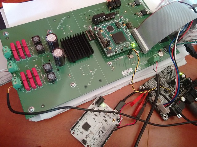
WM8804 in SW mode from the Arduino, generating the 49.152 MHz MCLK that the Axign AX5689 prototype needs.

Performance of the amplifier on the APx585 is exemplary and no sign of jitter other than PLL noise – no spikes.
I could tell you everything about the settings for the registers that I chose, but the application is very minimal, specific sort of scratch-an-itch and actually doesn’t help you with your particular application. If you want to look at the complete source code, check the source on GitHub.
If you do have a good idea for an application based on an S/PDIF receiver, such as a sort of programmable digital serial i/o interface, I might be willing to build that…
Decoding 176.4 & 192 kHz
The WM8804/WM8805 have a bit of a bug when it comes to the PLL settings for 176.4 and 192 kHz: the chip cannot discriminate between the two sample rates, and there is not one set of PLL coefficients that works for both. As a result, you have to know which sample rate you are expecting. Since I don’t always know, I wrote a workaround that tries to estimate how stable the PLL lock is and when not stable, tries the other set of coefficients. This actually doesn’t work all too well so I don’t remcomend using it. Another way I tried is to decode the ‘original sampling rate’ specified in IEC60958. That works ace with an Audio Precision set to transmit 176.4 kHz but as it turns out, almost no other device does that, so you cannot rely on that either.
If you have a better way, feel free to comment!
Hello,
Pretty nice blog with very honest and valued information. I’d like to ask you about one thing regarding the DAC processing control using a PIC. Some DAC performance could be optimized using different modes of audio data processing like: DATA recovered clock processing mode or PLL clock processing. What is the best method for your opinion to worth to be programmed for best audio quality? Kind of advantages or disadvantages of that methods. Thanks in advance.
Czesc Krzystof,
I’m not sure what you mean by data recovered clock processing. Normally, you’d run a DAC either from a clock master source or asynchronously. In general, unless a DAC has special facilities, you don’t want to run it asynchronously.
The master clock maybe a crystal derived local clock or a recovered clock from a remote source (like I’m doing in this post). Recovery always implies some form of FLL/PLL. Maybe you can explain what you mean by data recovered clock processing?
I was specifically thinking about chips like WM8523 with the possibility to control the chip by software and employing some PIC chip to program it over that interface. Than, using adaptive clock recovery (remote) generate the output reference clocking based on the frequency of the input signal – sort of 😉 So is it similar what are you doing here and you consider it as the best option? Another one could be using voltage controlled oscillator…
Hi Krzystof,
I’m regenerating the clock of the received signal because my source is external (the Audio Precision APx) and I want to run synchronous to my source.
Of course, if your source is local (let’s say a CD player or a memory card player) then I would remcomend to have a crystal oscillator.
The trick with interconnecting two devices with digital audio is always that there should be only one clock master. The others should slave and synchronise to the master. It doesn’t even have to be so that the receiver is always the slave! You can use some tricks, like I did with the System Two and the USB interface in my last post. Many devices have separate clock inputs and can output their data synchronous to that clock.
So, without knowing where your data comes from there is not much I can say, but this. It is pretty much the way most audio gear is designed and there are good reasons for it. Some snake oil companies have some very extensive PLL solutions for a problem that really isn’t significant – unless you have huge jitter problems you should be just fine.
Thanks. I was mainly thinking about CDR meaning Clock Data Recovery or Data recovery re-clocking. It needs to involve PLL I guess as well, but does it bring the improvement? I’ve heard that some high end audio manufacturers using this method.
There are two ways of dealing with accepting data from an external clock domain source:
1. You want to be clock master -> you have to Sample Rate Convert the incoming data
2. You want to be clock slave -> you need a PLL
In this post, I depicted scenario 2. I use a PLL not because I want to, but because I have to.
Now, when you re-clock data, from there on you have your audio on the recovered clock domain. Depending on the quality of the incoming clock and the quality of the PLL, this recovered clock domain can be better or worse than the original one.
You can’t say which one is better or worse without measuring source and recovered domains. High-end audio manufacturers will tell you whatever you want to hear, but it really is as simple as that.
By the way, the term Clock Data Recovery doesn’t apply to this – that is reserved for separating clock and data from e.g. a biphase coded signal such as S/PDIF.
So let say if I’d like to feed my DAC with optical toslink interface, where the clock is on the computer. So, in this case is it better to recover the clock from incoming data on the DAC side?
Better then what?
This is pretty interesting. It solves to 176 kHz problem. I ma looking to take I2S from an USB Amanero and also a couple of spdif’S RE-CLOCK and send out thru SPDIF. Take a look. I would be interested also.
https://groups.google.com/forum/#!topic/audio-widget/UpIcvEFxdRw
Yes, you can really use it as a good clock cleaner. When it came out, there was not much better on the market and the eye diagrams on the AP System Two were -pun intended- an eye opener…
Have compared anything else?
The eye diagram was in comparison to the CS8412. That part however, was so crappy that Cirrus (now owner of Wolfson) itself remcomends the 8805 instead.
Apart from that I’m not a clock fanatic.
I’ve had long intense (public) discussions with the jitter mob, but have never been convinced of the need for more than 100ppm accuracy for audio. They’ve yet to provide one calculation, DBT or any shred of evidence otherwise, and when they do I’ll join the band wagon.
It’s only audio, remember… 🙂
It really depends on your system Years ago I was working with Theta digital, and on a very high end system you could hear a difference down to about 10-15 ps jitter RMS. Most people don’t have these systems nor a tuned listening room. I currently have a Theta Gen VIII sr3. I also have Stax head phones that resolve better then any speaker system.
Did you take a look at that link I posted a while back? It turns out the 8805 sends out the sampling rate even before the PLL knows, through the I2S. And this is used as a means to switch the 8805 for 176 or 192. I am not a code writer so I barely get it.
“it depends on your system” is a classic non-argument. I give you the challenge of double blind proving you can hear jitter beyond 100 ppm, and apart from it operating properly, I make no assumptions on the circuit. Do that, and we continue the talk about audibility. I have been waiting for proof for over 10 years, so won’t waste any more time speculating.
The sample rate sent out by the 8805 is the metadata encoded in the stream. When I set the Audio Precision up that way, it gets recovered flawlessly. Thing is, only very few ‘normal’ signal sources output an an accurate sample rate metadata value, if any at all…
Hi, Great blog and insights!
Is it possible to read the PLL n (register PLL4) and PLL k (registers PLL1 PLL2 and PLL3) to determine the frequency of the incoming SPDIF signal that the PLL has synced to?
Best – Andres
Hi Andres,
Unfortunately not. With the same PLL values it manages to track both 176.4k and 192k.