What’s a hobby desk without a good ‘scope? A car with no engine. A fondue with no cheese. A church with no minister. A threesome with no, erm let’s get back to the topic.
Now, I have a good Tektronix rig but it’s a bit unwieldy to have in the house. So a nice scopemeter would do 99.999% of the time. Besides, it can also serve as a -very- good multimeter. Want!
Caveat: I have worked often with scopemeters and I love ’em. I know quite a few folk who don’t. It seems to be a matter of taste. So try one and decide which side you’re on.
I managed to shoot a broken Fluke 123 for beer money on the old Fleabay and it arrived pretty soon after, and it was immediately obvious: this poor bugger has lived a hard life. It was described as ‘does not power up’ which I prefer to ‘does power up but does not do XYZ’. The latter can give you big trouble, the former means it’s either a simple fix or simple to find out that it’s dead forever. In any case, simple. Simple is good. Simpler is good-er.

The Fluke 123 as it was advertised on eBay
The second thing I noticed is that it had a weird switch attached on the bottom left side. Bad news. Someone had been tampering with it in a very unprofessional way.

Fluke 123 Scopemeter in ‘service position’
Time to undress it and get to work. Now, credit where due: before buying the scopemeter I did a search on the internet for service manuals and found the one for the Fluke 123, downloaded it and read it from A to Z. And seriously, this is what service manuals should look like. Not just a schematic, no, explanations of what each circuit does AND a complete fault finding guide with extra care of what to when it doesn’t power up! Winners!
The first problem was not that hard to find: a broken diode with a very dodgy repair.

r badly borked diode
Yeah, that one let out the magic smoke so soldering the die to the cathode is not going to do very much (which is what was done to it when I found it!). Now of course the question is why did the diode break? Not knowing the answer I ordered 10 diodes and hoped they wouldn’t all blow up the same way. And they didn’t. The first replacement diode is still in there. Anyone need 9 diodes?

The broken diode in the power supply
As you can see the diode was part of the switch mode power supply for supplying juice from the charger.
Unfortunately, applying a charger voltage still only yielded a gut-wrenching whine from the flyback transformer. Not there yet!
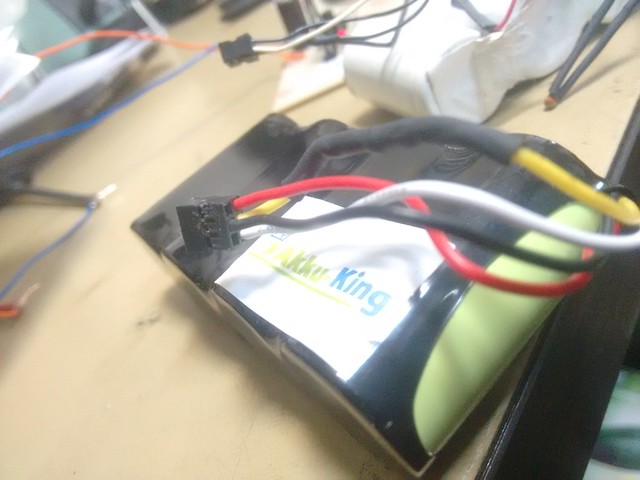
Simply following the service manual’s suggestions led me to check the battery, its wiring and all related components. The battery turned out to hold no charge even when charged externally, not very surprising for its age. But then I found that the battery current measuring resistor (3x 1Ohm in parallel) measured 3.8 kOhm. That is plain odd.

Battery current measuring resistors
Now, without a proper voltage across these resistors the P-asic thinks that the battery is either full or over voltage, not that it’s empty so it tries to start up. The battery does not allow that it since it’s empty and even though the adapter circuit works, it’s not used (because a full battery is assumed present). So the whine is the flyback converter desperately trying to run on a dying battery with little help from the adapter since its supply isn’t running as the D-asic thinks its help is not necessary. Poor little flyback.
Resistors replaced and the whine is gone! Instead we get a nice beep from the loudspeaker indicating the software bootloader is active, and a second or two later I hear the relays in the input pathways click. Good news! This sounds like a working scopemeter! Alas close but no cigar… the screen is on, the backlight works, but it’s all black…
This is where you are on your own as the service manual says ‘sorry dude, the screen is not serviceable’. In other words, Fluke bought it from an external supplier and didn’t develop it by themselves. And you really can’t expect them to write a faultfinding guide on a part they did not design.
Connecting my trusty Tektronix told me that there is activity on all the connector pins such as framesync, line sync, the voltages are all good, actually it should just work. What in the world…
And then I saw it.
A drop of soldering tin, I will maintain until my dying breath not dropped by me (I had the display board covered), had fallen on the board. Right across a bypass capacitor of some sort. And probably shorted a nice data or supply line. Simply scratching it off with a screwdriver was all that was needed, and voila!

She lives!
Time for a little dance; you just earned about five hundred bucks!
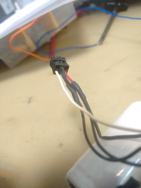
Oh and for those who wonder about the weird switch; it turns out the foil cable from the keyboard had been damaged. Probably by the same person who broke the diode. Simply melted one conductor on the outsdide. So a crude makeshift power switch had been added. I instead fitted an iPhone switch under the real power key. Of course the best solution is to simply order a new foil from Fluke. I might do that one day, but it works just fine without and not only are they expensive, it’s hard to order them. Fluke if you’re listening: put up an online spare parts order page!
I did some reading on the internet and it turns out these scopemeters are not at all happy to live with a fully discharged battery. The battery needs to hold some charge and build up some voltage quickly because the charger supply can deliver quite some current. That is probably how my sample blew its current measuring resistors. They were rated at one Watt each, so it had managed quite something to break them. The replacements I fitted are 6x 2 Ohms at 2 Watt each. It was quite a snug fit.
The diode, I think, was simply damaged by brute hands trying to find the resistor problem. I did not look like it had been blown up electrically.
Next step was to order a replacement battery. It arrived but didn’t charge at all. Again service manual to the rescue: wonderful, the chinese manufacturer had miswired the plug. Well that was an easy fix and now I can go for hours on battery power. That will be great when doing work on the car.
As I didn’t get the original power adapter with the scopemeter I dug into a box and bodged one from a wall-wart and a battery plug. The Fluke adapter port is quite particular in that the outside is + and the inside is -, so do take care there, although plugging it in the wrong way does not damage the meter (or so I heard. Ahem.).
So, with some luck but mostly a great service manual this new buddy of mine has been given a new lease on life and I have regained lots of desk space 🙂
You gave me confidence to repair my Scopemeter 123, which has been my electronic eyes & ears these past 14 years. Many thanks. Replacing the batteries recently with size C NiMH (bad idea) managed to lose battery power. It still worked on charging input. Downloaded the service manual and was able to troubleshoot this. Turned out I must have shorted the + battery terminal to metal shield ground and taken out current sense resistors R504, 506, 507. Replaced these. Next, discovered I could buy NiCd size CS at RS components (UK distributor). Made up new quartet of cells with recycled thermistor, thermal fuse , lead and connector from old pack and the 123 is now restored.
Great to hear! 🙂
Yeah there is something fishy in that supply circuit. When I leave my battery in and turn the meter off it does go flat after about 12 hours. Not great but I can live with it. However, when I reconnect the charger it won’t power up until I remove the battery. So I mostly keep the battery out when the meter is on the desk.
I’m thinking to analyse and re-do that circuit so it can live with NiMH or even Lithium-Ions. When I can find the time…
I thank you for your posting with valuable info.
I am still stuck on not being able to power up the fluke 123.
I get a flash of back light and hear 3 faint clicks of a relay and one beep.
The screen will not stay on, but seems it is trying. I replaced a bad cell on the battery pack and have the original charger connected. Without the charger the screen will not flash (I have over 5V from the batteries) but in this case there is non stop relay clicking even when you try to shut the switch off . I have not found the resistor bank yet. That will be next.
any suggestions on the back light not staying on?
It sounds like your flyback converter is not starting up properly. The beep means at least the D-asic is on and made it through its bootloader.
Do you have the service manual? It has a step-by-step guide of fault finding (IF this, then that, ELSE blah blah).
There is a crap SM and a good one. This is the good one right here. http://elektrotanya.com/fluke_123_scopemeter.pdf/download.html
Let me know if I can help further.
Hi, my fluke 123 Scopemeter is playing up on me, it powers up nicely but it won’t test anything, I gave it a refresh and it’s still the same…sometimes it would display waves and give a reading, the numbers would be changing quickly for no apparent reason then disappear leaving the wave line frozen on the screen.
Hmm. That’s not something I’ve seen, but I’ve heard about the newer Scopemeters (the 4 ch colour ones) having this trouble. In their case it’s the M-asic making bad contact with the board (and you have to be a BGA soldering guru to fix those).
Have you gone through the service manual? There’s troubleshooting guides that help to identify the offending component. This is a tricky one – it could be the ADCs, the D-asic or the T-asic. The last one, trigger-asic, is where I’d start given your problem description. Check contacts and measure supply voltages first. Then, go through section 7.5.6 of the service manual and check all the wave forms. If that test passes, I’ll be very surprised. If it fails, post another comment and we’ll take it from there.
Good luck!
i have one of these with a weird problem that i’ve been trying to fix for a few weeks. continuity on the A input gives a constant beep like it’s shorted.
when you first switch to cont mode, ohm reading starts at about 80ohm and drops toward 0 at a good clip, and when it reaches about 50 or so the cont beep starts and continues like the leads are shorted. when it hits 0, the display reads OL (Open Lead) but the beep is still constant.
the A channel seems to work ok in other modes, but seems a bit noisy when looking at a waveform compared to the B channel, and i see a waveform in the A channel for a minute or so after boot until it settles down. i’m guessing this is related to the falling ohm reading after boot on the cont mode. after it sits for a bit, voltage and resistance readings do match up when compared with my other fluke 87v meter or the B channel.
any ideas?
Hi Doug.
I just recently started using my (early 2000’s) ScopeMeter 123 after battery replacement.
I had to replace the NiCad with NiMh but that seamed to go well.
But I’ve discovered that I have the same issue you had with the continuity on channel A.
In my case just waving my hand over the top of the scope with no leads attached seems to induce a short on channel A while in continuity mode. The meter plays like a music instrument for a few seconds and then goes into full tone until I switch out of ‘continuity’ mode.
Were you able to resolve this issue?
Anybody else reading this know anything about this issue?
Thanks in advance.
Hi Doug,
That’s a tricky one. I’m leaning towards suspecting the ADC on channel A. The time constant suggests something of a capacitor but I can’t work out which capacitor would be in the signal path for DC continuity measurements.
There is a bunch of very high precision (50 ppm) RC networks around the C-Asic feedback network that merit investigation.
Now the good thing is the commonality between the channels. You could take the front end signal of channel B and hook it to the channel A ADC. If now you have a good signal on channel A, you know it’s somewhere in the front end. And so on and so forth.
Many other things you can measure by sticking a signal on both A and B and following the signal paths, assuming that B works fine.
That’s all I can think of from here… good luck and do report back what you find please!
Best,
– Remco.
Hi all
My old and trusted 123 scopemeter started ,lately, to fail turning on the LCD backlight, last week I noticed that the battery compartment is very hot and a bad burning smell , I checked the battery ,no problem.
I took out the Main PCA, watched it ,but found no burned parts.
Without connecting the keyboard and LCD I connected the battery ==> nothing unusual, then connected the charger still nothing unusual, the battery is charging and nothing gets hot.
Next I shorted PINS 14,15 (ON KEY) ==> got 1 beep ,after a while the electrolytic capacitors ,between the battery connector and flyback transformer started to get hot and very fast got to be very hot .
Do you have any idea of the cause and the way of fixing it?
Thanks, Yudi
Sounds like those electrolytics are bad. Happens a lot in SMPS circuits…
Hi Yudi,
Did you run through the fault finding guide in the service manual? Where did it point to?
Hi remco
Yes I did, Here they are:
TP504 5.26V
TP577 from -10V to -7V (not steady)
TP576 -1.5V
TP574 0.6V
TP573 0.7V
TP572 3.5V
Then I connected my even older Tektronix (5223) to TP552 and saw a noisy square wave (I don’t know how to insert a picture).
I disassembled capacitor C563, because it was the hottest one, and connected a 470uF/10V (this is the closest I have) .
On powering on, a thin copper trace , which goes under this capacitor. started to GLOW ….. HMMMM!!!!?????
Well… I checked, it goes to pins1,39,40 of the P-ASIC (it should carry -30V).
Do you have any idea of what’s going on?
I have pictures , but again, CTRL-C CTRL-V doesn’t work
I’m, really, in a great need of help
thanks
Hey Yudi,
Sorry for the late reply, I was travelling.
According to the SM,
=> none of your voltages are correct => step 2 (still, double check the rectifier diodes)
=> did you?
So you did observe a square wave, but did you see the triangle on FLYSENSEP?
I’m going to assume no after reading your story.
You need to check R504, R506, R507 (battery current
sense resistors) => the same resistors that were broken in mine so a definite hint there!
And then, check or replace V554.
Keep going systematically through the fault finding guide… we’ll get there!
Thank you for the great info.
Anyone knows where I can get the service manual for fluke 99?
My unit does work with 4 C batteries, but when I connect the charger and try to charge its new NiCd battery, it doesn’t charge the battery. Any suggestions?
Hi Drake,
The service manual for the 123 is all over the net, however I’ve now also uploaded it here:
https://itsonlyaudio.ddns.net/index.php/s/kCB7clkhE4C8fBJ
As for the 99, I don’t know. I don’t have one. 🙂
As a rule of thumb, I’d advise to start the scopemeter up using the power pack. Then, connect the batteries and see if they charge. If you do it the other way around, it often won’t work.
Best of luck!
Reg. Fluke Scopemeter 123 noise.
Hello gents
My meter has gone bad. That is: At first sight all seems OK. It powers up, beeps, relays click, display lit (no lines or bad pixels), signal comes on, but: A LOT of noise, approx half the screen on both channels, regardless of range and timebase setting.
Holding one probe reveals a “hum waveform” in the noise, so it does trigger.
Having fried BOTH channels is unlikely, so my guess is that some common ground reference may be missing.
The trouble started shortly after mounting a NiMh battery. This aftermarket battery was wired wrong and had a false Rident resistor built-in, but it seems to be the rule, so I corrected it according to many good web leads.
The Fluke SM is quite clear in battery terminal numbering on the schematic. But the corresponding numbers in the battery plug are certainly not.
Could it be, left to right, 1, 3, 5 top row and 2, 4, 6 bottom row as seen on to the PLUG rear (where the wires come out), and “top/bottom” as fitted in the meter (“top row” being closest to meter rear side) ??
I wish I could have attached some pics.
Hi,
Looks like the diagram you drew up here at EEVBlog is correct.
Here is my old battery:

The notch at the top of the connector fits into a slot in the scopemeter socket, towards the back (i.e. towards the top, if the scopemeter is lying on its screen).
I wired up the new battery similarly (although the connector has no notch)
The noise problem, I think, is unrelated. I did put a wrongly wired battery in, and nothing bad happened, it just did not charge. The fact that these two incidents happened at the same time may be a red herring.
Best,
– Remco
hello,
my fluke scopmeter 196c was working fine but suddenly it seems like it got stuck on the reset screen.
I turn it on and the screen works just fine, but when I hit any button nothing happens. So I can’t display menus at all. F keys don’t work either.you can hep me plz
best.
Will be happy to help. Send me a message through the contact page and I’ll make you a no fix, no fee offer.
Hey guys,
I have a fluke 123 scopemeter with no back light. When I turn it on, the LCD presents data. All functions seems ok. Its just the damn light. I wanted to see what you guys think before I attempt to open her up and start digging around.
Thanks for any input!!
Tony
Hi Tony,
The main function of this blog post is to stimulate you to open it up and find out what’s wrong with it. The service manual is excellent. So go for it.
If you’re not sure of what to do, we’ll be happy to make you a no cure no fee offer.
Hello,
I have the 123 nearly 15 years and has worked without problems until a month ago.
When I turn on, the screen don`t work, but backlight is very few see the to work.
Do you have some idea of what it might be like to …?
Hi Mike,
The main function of this blog post is to stimulate you to open it up and find out what’s wrong with it. The service manual is excellent. So go for it.
If you’re not sure of what to do, we’ll be happy to make you a no cure no fee offer.
Thank you very much.
The 3x smd sense resistors can they be replaced with just chip resistors?
Cause have hard time on finding res frc01 1206 5% 1e
Whhat should be a proper replacement .?
Thank you very much
I can’t advise you there. I just used whatever I had lying around and 5 years on, it hasn’t exploded yet.
Wow, Thank you for putting this page up. I have had my meter since new and its about 16 years old. I have only used it a handful of times and it lives in the original box. I would try to get it out every so often and plug it in to charge the battery. Well, i got it out last week and all it did was beep once and I could see the backlight is on. I checked the battery voltage and it was around 4.6 volts. I have since downloaded the manual and tested every thing i could. I started the troubleshooting at “Software Runs, Test Tool not Operative” (7.4.3) in the manual. I tested all the MS401 to MS422 and everything was correct EXCEPT for MS404 (REFPWM1) which was less than .5v and noisy. The other thing that was odd was on T600 the half rectified sine wave was 8v p-p but the frequency was 74kHz. Now, something to note, is that I did these tests without the battery connected.
When I got to the flyback checks I could not locate TP576, but all the other TP57x were correct. (pretty much everything I have tested has been .2v higher than listed, 3.3v were 3.52, 5.0v were 5.2v etc..) Also, the sawtooth on V554 was present and operating at 120mV and 138kHz. Could that be because my battery was not connected?
I also tested the keyboard MS432 through MS437 and it was perfect.
I’m sort of at a loss here… I had to return the scope I borrowed, but hoping to snag one on ebay. (couldn’t hurt to own two scopes lol).
Cheers
Hi Sam,
The main function of this blog post is to stimulate you to open it up and find out what’s wrong with it. The service manual is excellent. So go for it.
If you’re not sure of what to do, we’ll be happy to make you a no cure no fee offer.
I’m having the exact same issues as you as I am going through the trouble shooting. My MS404 is <.5V and t600 half wave is at the higher frequency. The wave is there on startup but then stops completely. I have tried this through the power adapter, through battery, and through both all the same. Will keep investigating let me know if you have any luck.
Okay. Thanks
My 123 display has a large dark patch covering most of the LCD like a large screen burn. It is just legible but difficult to use. Edges are OK. The backlight CCFL is OK. Also has squiggley yellow marks around the edge outside the active LCD area. Suspect the glass panes are delaminating.
Not found anyone else with this problem using Google.
Suspect that a new display is the only solution but not worth paying official price for it so has anyone found an OEM solution? Or have to buy a dead 123 on eBay and hope the screen is good. Or get a Smartscope which is half the price of a new display.
Not impressed by this 1997 unit’s reliability as have already had to replace the battery, the keyboard foil, the battery current sense resistors and a 32kHz crystal early on in its life and was not used much. Have not been able to get it running on batteries for years.
I got a F123 which is not much used and in original box etc (about 10Y old).I recently used it to record the utility supply and left yesternight charging. This morning I connected it back to utility and powered on , I heard some sharp tone (like smps loading) from scope and display didn’t come up. The beep appear though. I could but connect it to laptop (flukeview) and retrieve the records saved.I also tried to do some setup ( voltage setting) through screen shots , But the reading stays 0V on both channels though probes connected to utility. I am not sure if its display back light converter or Flyback alone. I disconnected the battery and powered with charger but same result. I got the SM and will have a look , But any suggestions welcome !.
my fluke 123 cannot mesuring (does not give any) all functions is work
After leaving my Fluke 123 unused for a few years, it isn’t working anymore. After switching on, it keeps on beeping. It seems like it starts up, gives one beep, switches off, starts again, beeps, switches off, etcetera. I did quite some measurements according to the Service Manual, but the problem is not very clear to me yet. A lot of voltages drop, when the device switches on, and come up back again when it switches off again.
In SM 7.5.2 nr 3a1 my device is not showing what it should be. There is a saw tooth, but is about 110kHz, and only ~30 mv maximum. It also looks very irregularly shaped. Like starting up with some sine, combined with the saw tooth. From there I’m a bit lost. What does underloaded outputs mean? And the next point, V552 and V553 don’t seem to be on the board.
Anyone an idea? Would be really appreciated.
Edit: the above signal is before the beep. When it beeps, this sawtooth becomes 25kHz, with a peak of 380mV for a while, and then drops back down.
btw, behavior is the same when running on battery and charger
Hi Menno,
The main function of this blog post is to stimulate you to open it up and find out what’s wrong with it. The service manual is excellent. So go for it.
If you’re not sure of what to do, we’ll be happy to make you a no cure no fee offer. But honestly, modern units cost $300 or less, so unless you drive Uber it’s just not worth your time any more.
Mine has the Display degraded, Any idea where can I buy a replacement or if it could be connected to a PC as a display?
You can replace the CCFL with an LED backlight and replace the zebra strips if you have black or missing lines.
The display module is not meant to be serviced as Fluke bought it pre-assembled. Not sure if spare parts exist.
You can grab screenshots over the infrared port but every frame takes ~5 seconds, will not be workable as a functional scope.