Yes, I am still alive. Sort of. 🙂
This should involve only about 3 people in the world, but hey, I should blog more even if the relevance is negligible. If this helps 1 person, I’m glad.
Not recently at all I bought a bunch of Yokogawa A1D03B supplies from Pollin (originally meant for HP printers). The idea was that they are nice to supply small / medium amplifiers for active loudspeakers. The output is 31.6V but I needed about 24V.
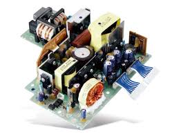
The pinout of the connectors is available here.
Like any switching power supply, it needs feedback through an opto-coupler. I have designed some of these in the past and even if this one is a bit more complicated, the only part I need is the feedback.
So I started out tracing the relevant part of the board. There are 3 opto couplers sitting together, and OC3 seems to be the one related to the 31.6V. Obviously you do this with a pencil and not a permanent marker, unless you are a stubborn idiot.
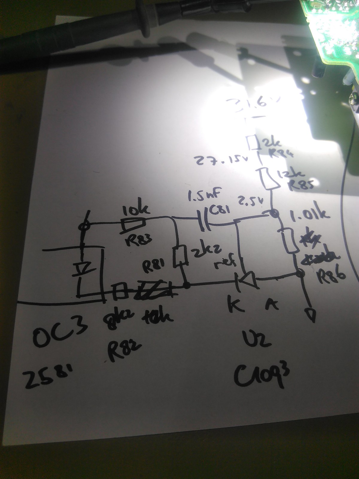
This is roughly the feedback circuit
This should be about 98% correct, and is good enough because we have found the feedback mechanism. About 2.1 mA comes back from the ‘high voltage’ through the feedback resistors R84-R85 to the reference node from which R86 sets the current.
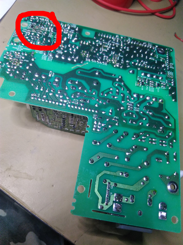

R84-R85 are here
The easiest way of changing the feedback is swapping out R84 and R85. They are relatively large (0805) and easy to get to. By the way Yokogawa, thanks for numbering the components. Nice.
So,
Vout = 2.5 + 0.00208*(R84+R85)
or to put it another way
R84+R85 = (Vout-2.5) / 2.08mA
I chose R84 and R85 to be 4.7 kOhm as I had a reel literally lying on the desk and this would give me about 22V. Indeed it turns out the voltage was sitting roughly at 22.7V which is within the tolerance of the components.
It turns out the 16 V-/0,5 A is derived from the same feedback as that now scaled to 14.4V. Whatever. The 5V and 3.3V lines remain the same. The supply is quiet, runs with no load and has an active shut-off which brings the output voltage to zero when switching off, even with no load. All in all a quite useful supply for little projects.
Update Oct 15, 2017:
I have replicated the procedure on a bunch of similar power supplies and it always works the same way:
- find the opto-coupler
- find the voltage reference
- trace the relevant part of the circuit and find the resistor coming down from the output voltage to the reference voltage
- do the math similar to above and find the new value for the voltage setting resistor
- profit!