Usual disclaimer: not my main work, we do not accept repairs. (but by golly, they do seem to find me).
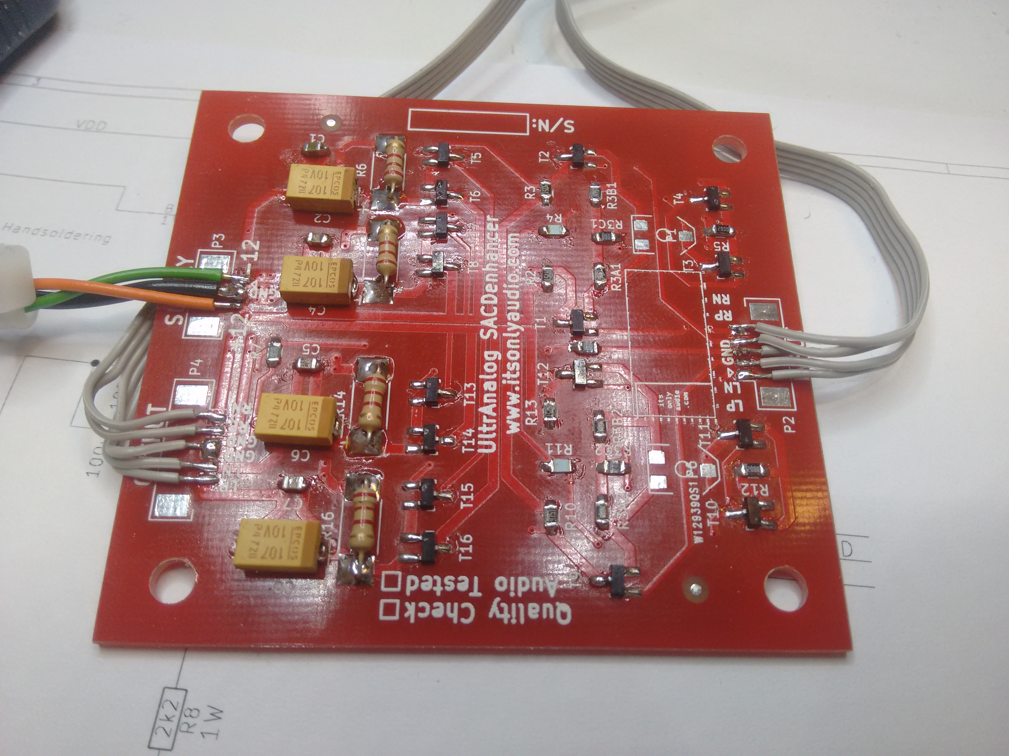
In order to save anyone working on this amp a bunch of time, here is everything you need to fix this amp. The circuit is about as simple as my old sacdenhancer, so no need to go into that.
Service manual
https://elektrotanya.com/harman_kardon_citation-eleven_11_sm.pdf/download.html
User manual / specifications
https://www.manualslib.com/manual/279186/Harman-Kardon-Citation-11.html
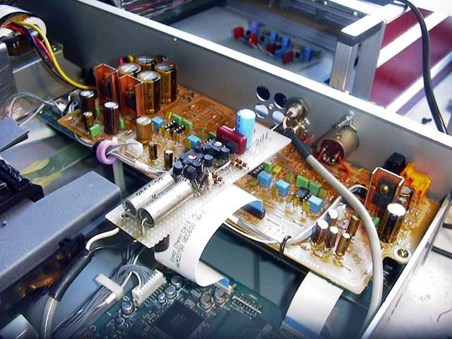
PCB holder
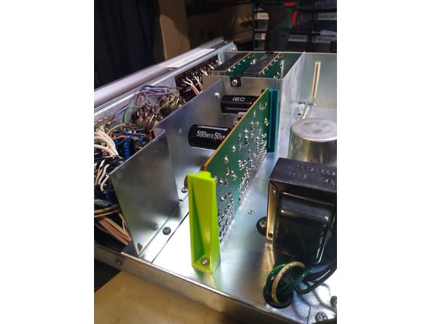
A very nice construction style. Unfortunately 40 year old plastic gets brittle and I broke one just by looking at it the wrong way. So here’s a 3D print model.
EQ section hum
The equalizer is open loop and has no PSRR, so you can’t expect better than 600 uV of hum overall (spec: -80 dB relative to 6V = 600 uV).
If the EQ section picks up more than 1 mV of hum with the 60 Hz slider all the way up and maximum volume, this is due to L601 picking up stray magnetic field from the mains transformer (L601 and C607 are tuned to 60 Hz).
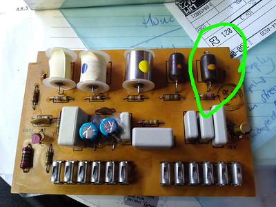
L601
The citation eleven on my desk had two different L601 coils in each channel and I didn’t know which one was the original. But one was wound in such a way that it picked up over 6 mV, i.e. probably a replacement not wound symmetrically. The metal shielding is not effective on magnetic fields and in fact amplifies the field lines as it creates a short circuited winding. So the coil should be magnetically shielded and wound symmetrically.
There is a replacement coil available that is shielded correctly and brought the hum well under 300 uV. I remcomend it over the original, even.

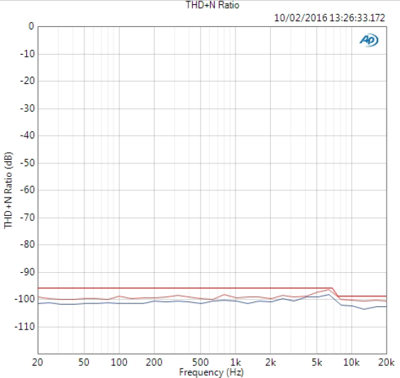


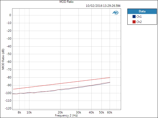
 So let’s pit this thing against an opamp stage and see what happens. In the left corner, representing the heavyweight class, the Analog Devices OPA275. The challenging contestant, some ridiculous discrete design from some dude in 2003 thinking they know better. All that and more, in part 2…