There is one thing the older Audio Precision System One and Twos don’t have which can be quite annoying: they don’t have USB host functionality. And given that all the processing and clocking happens inside the unit, the control software can’t reroute the digital signal generator to a USB output.
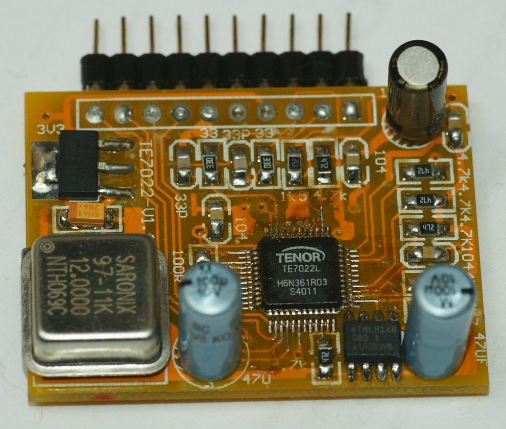
Tenor T7022, an often-encountered USB receiver. Does it do bit correct feed-through?
Of course you can use a PC to feed the USB sound card and measure the output with the AP, but then you don’t have the generator signal to do e.g. sweeps or automation. The best of course would be to somehow get to a full loop starting at the AP signal generator back to the analyzer. After quite a lot of tinkering, I managed to do just that.
The idea of sending the AP signal to the PC and letting the PC send it to the USB sound card is pretty trivial. Where it goes wrong is at the clocking stage – how can we manage to keep these devices in sync with each other?
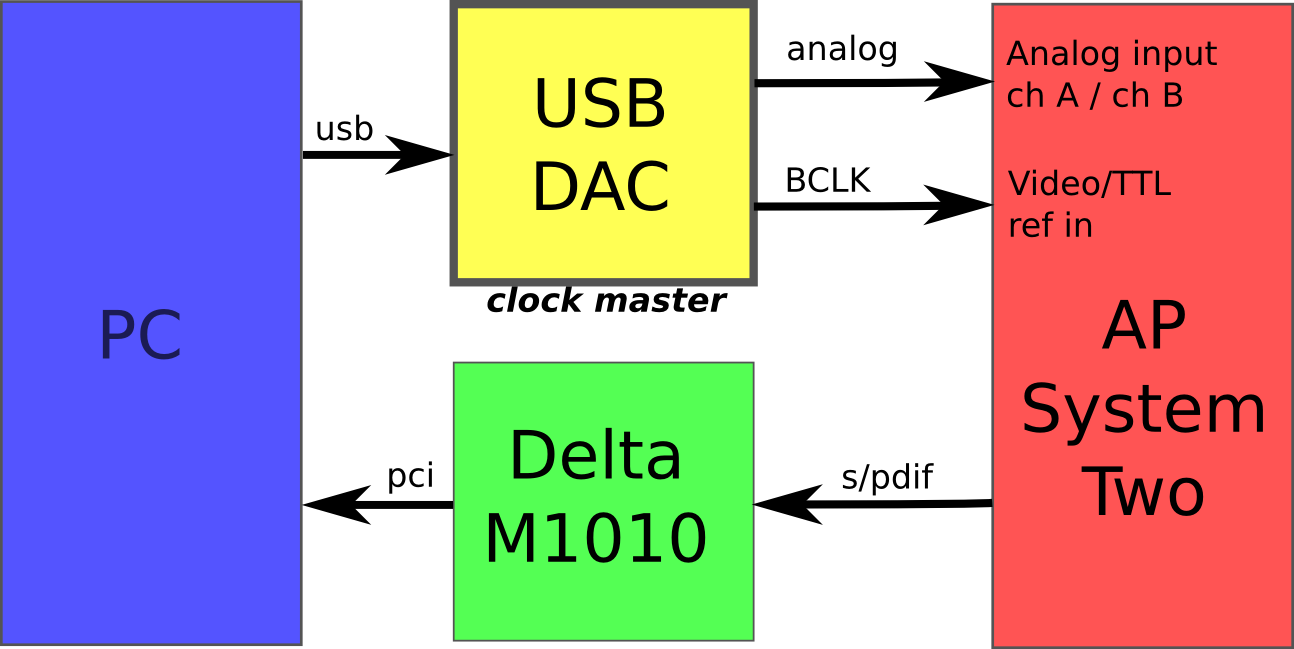
The clocking scheme
Here’s how it goes. As we have a loop, somewhere we need to have a master clock. The AP would be the best candidate for a stable clock, but the USB sound card usually has no S/PIF input to sync to, and can not be trusted to run synchronous to the PC either. Taking that into account, the USB device should then be master and the others have to sync to it.
So, the clock loop goes: USB DAC -> AP -> M1010 -> PC -> USB DAC
And the signal loop goes: AP -> M1010 -> PC -> USB DAC -> AP
The M-audio Delta 1010 serves as the input device, capturing the generator signal from the AP digitally through S/PDIF into the PC. Of course, any sound card with equal capabilities will do. Using mudita24 the M1010 can be switched to clock off the incoming S/PDIF signal.

M1010 slaved off the S/PDIF clock
Now, inside the PC, we have to string the M-audio and the USB sound card together. This is where jack comes in. Using the control GUI qjackctl it’s dead easy to set up.

Main GUI -> Setup…

input is the M-audio delta 1010 capturing S/PDIF
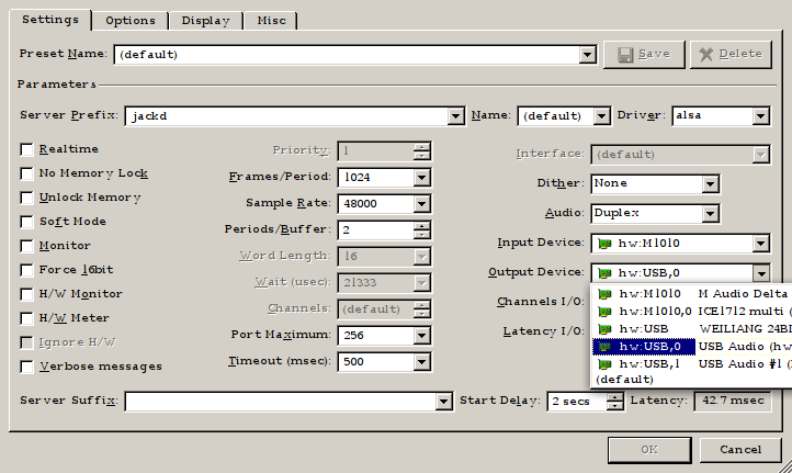
Output is the USB D/A converter
All you have to do now is press Start, and when jack runs, you can now go the connect window and patch the S/PDIF inputs to the output!
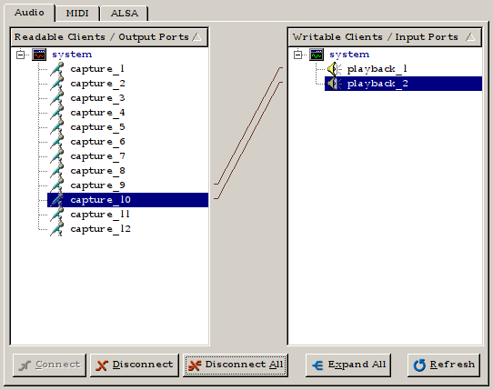
S/PDIF inputs (9 and 10 on the M1010) routed to outputs 1 and 2
Now, you may wonder how jack is doing the routing, is it trying to sample rate convert and do we lose our bit correct feed through? The answer is no. Jack simply copies input to output. If the input rate exceeds the output rate, jack will drop samples. If the output rate exceeds the input rate, jack will insert zero samples. So, if we get the clocking right, we can expect bit perfect feed through.
The final step is getting the AP to sync to the USB sound card. This one is a bit tricky and took quite some time to get right.
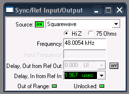
The Audio Precision has a Sync/Ref Input/Output function panel that can take sync signals from AES, video frame, or… a square wave TTL input. That’s what we need. In the USB sound card the signal is converted to I2S, so we have a word clock.
Slaving to Word Clock didn’t work all too well.
However, the sync input PLL is pretty picky and it isn’t happy with the stability or the lowish frequency of word clock. I tried with two different APs and neither of them will get a stable lock.
To test whether the clock rates are stable, I generated a constant value with the Digital Generator in the AP (with dither switched off!) and looked at the I2S signals on an oscilloscope.

772k waves stable, but then…
Using my brand spanking new Rigol DS1054Z it was then possible to create a pass/fail mask around this constant bit pattern, and then sit back and see if it will remain stable. Alas, after about 20 minutes, we get a fail.

FAIL – a missed sample
Of course this can only indicate the case where jack inserts a zero sample and not the case where jack drops a sample. But still it’s a fail.
Taking another shot at synchronising the AP to the USB D/A converter I tried the Bit Clock signal instead of Word Clock.

LOCK to BCLK
Bingo! The Bit Clock is good enough for the AP to lock to. Note though that you have to indicate the clock rate to a very high precision (3.07235 MHz). You need a good frequency counter to find this number. Luckily the Rigol has a hardware frequency counter with high enough precision.
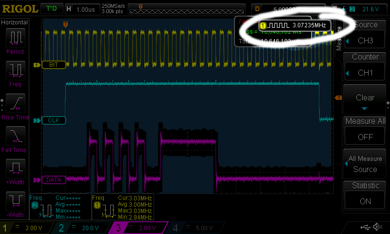
High-accuracy BCLK measurement
This is the number to enter in the Frequency field of the Sync dialogue box. The other thing to do is divide this number by 64 and enter that number in the digital I/O Sample Rate setting. In this case 3.07235M / 64 = 48.0055 kHz.
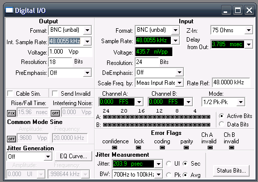
Set the right output sample rate: BCLK/64 as accurate as you can
Now we actually have a stable signal, let’s try to run the pattern mask again.

10M passes, ZERO fails and counting
After about 10M passed waveforms (a good two hours) I got bored and took the screen capture. So far there have been no fails!
Now that we have clocks locked, the next question is: are we able to get bit perfect feed through? The constant pattern seems to indicate so, but it’s not full proof. A tool that can help here is the ‘walking ones / walking zeros’ test stimulus the AP can generate. You have to set the number of samples per step to 1. Then capture the I2S output and walk through the signal to see if the bit is stepping forward at every sample.
A ‘trap for young players’ is that many USB devices, including the one I had, don’t set full digital volume when inserted but rather something like -20 dBFS. So take care to go into e.g. alsamixer and ramp it all the way up.
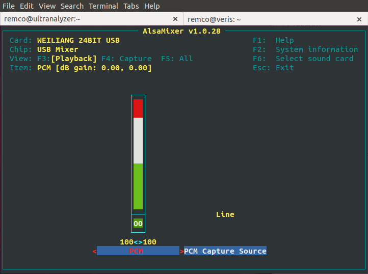
Turn the digital volume all the way up to 0dBFS for bit accurate feed through
Of course, a digital volume control would have affected the digital data. Now that it is set to 0 dBFS, we have a chance of getting bit perfect feed-through.

Walking zeros test signal
And that is exactly what we get at the output. I was puzzled for a bit when I noticed that I got two samples with the same value before the zero bit stepped on to the next position, but of course we are looking at a stereo signal, so you see the left word of value 1, the right word of value 1, and then the left word of value 2, etcetera.
When you set the number of samples per step to 48k so that it takes one step per second, you can see with your own eyes that the right pattern comes out.
If you count right, you can see the AP is generating 18 bits and verify that with the Digital I/O screen capture above.
So there we have it. We have clock sync and data integrity. It may be a bit convoluted and not as easy as with the newer APX series or a Dscope, but it is certainly possible to test USB sound cards with an older Audio Precision.