About four and a half thousand years ago, I designed (SA)CD player output stages with vacuum tubes and at some point came up with a transistor version, called the SACDenhancer.
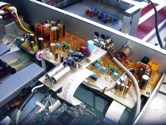
Original version, ca. 2003 AD
In double blind tests this was a big preference over the built-in opamp solution. It spawned off a plethora of discrete output stages from various manufacturers and modification shops that were all the rage in the day. I had some pretty good spectrum analyzer but never could find definitive measurable differences between the standard output stage and this one.
Fast forward 15 years and I’m still getting requests for this design, so I had a PCB made. Both fabrication and measurement capabilities have moved quite a bit forward in the meantime.
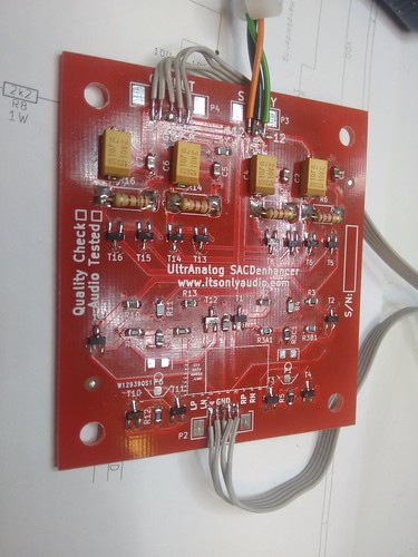
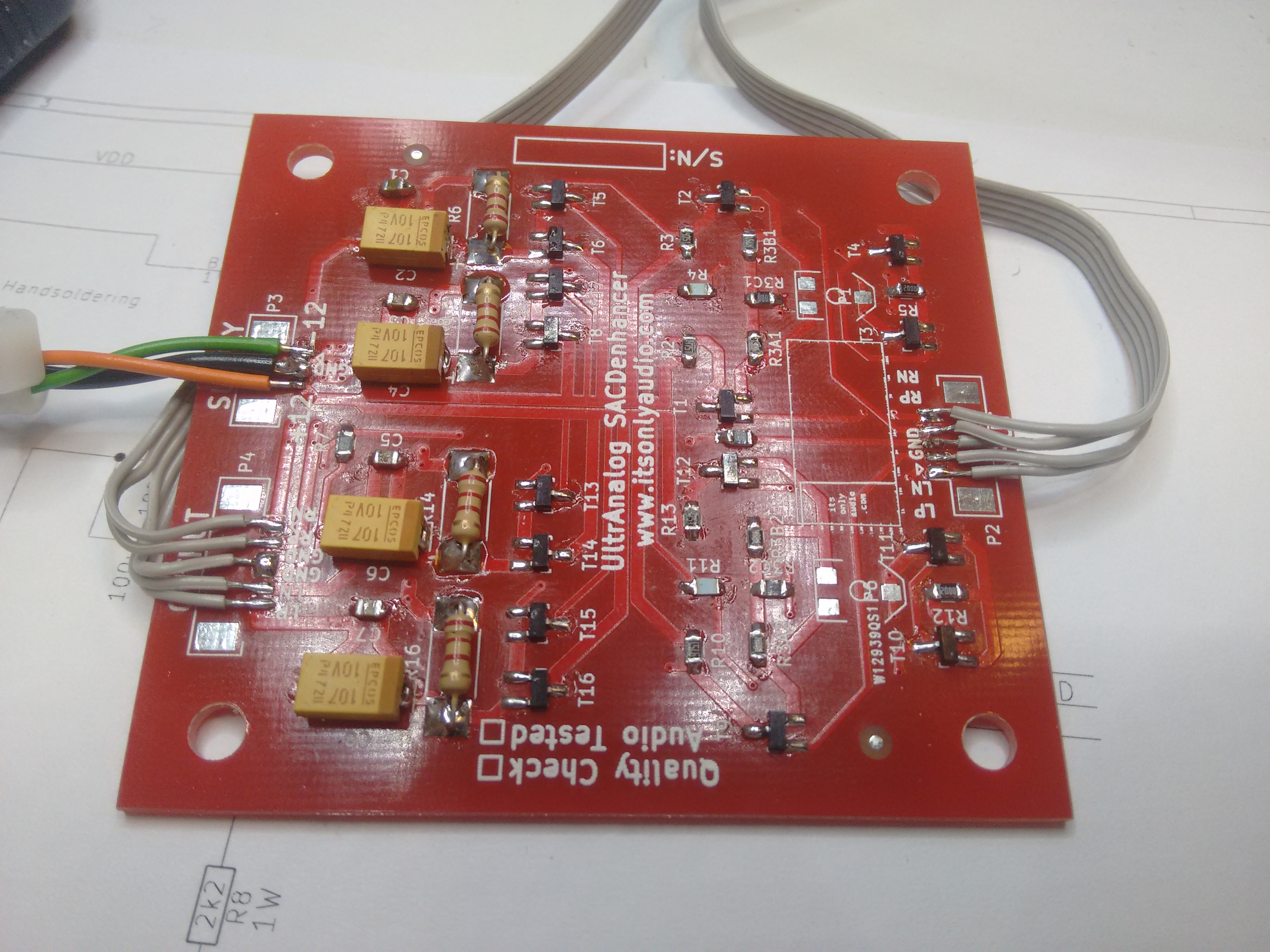
Reboot, ca. 2016 AD. How nice you can now get solder mask in ‘UltrAnalog’ colour palette from China.
This version follows the original schematic but adds a second output stage for fully differential processing. As such the schematic stays ridiculously simple – just a long-tailed input stage and emitter follower output. Couldn’t be simpler (I tried. Believe me. It wasn’t good).
Basic performance
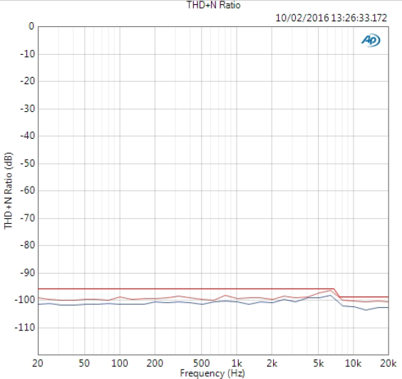
Test conditions unless otherwise specified – 1V rms differential, 997 Hz input, AES17 measurement filter, unweighted
THD+N : -99 +/- 0.5 dB
Best THD : 109 dB @ 0.7Vrms input
SNR: 100 +/- 2 dB
Frequency response linearity: +/- 0.02 dB, 20 Hz – 20 kHz
Gain linearity: +/- 0.025 dB
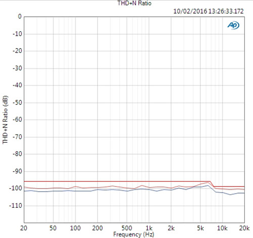
THD+N vs. Freq
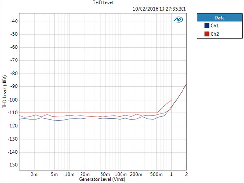
THD vs Level
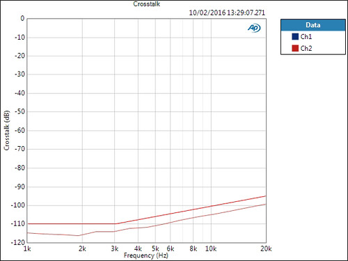
Crosstalk
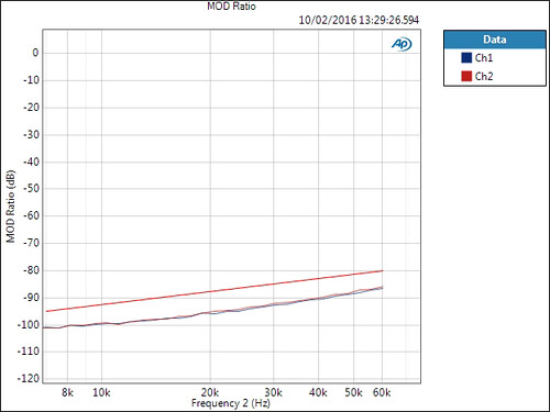
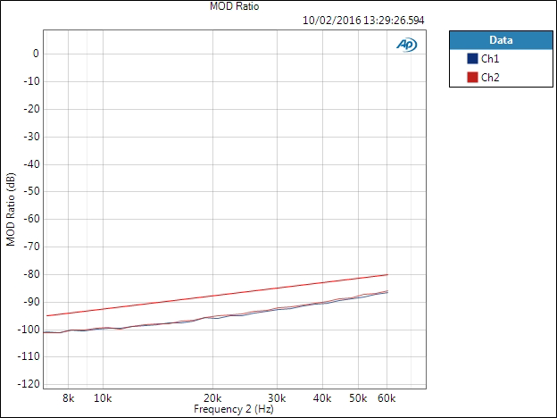
Intermodulation, 1k sine 1:1 with swept sine from 60 kHz to 6 kHz
Good news – the performance indicators are all green: no defects. This is pretty much as well-behaved as you might expect from a discrete design. But while it clearly says there’s nothing wrong with how this will sound, it does not prove it will sound better than an opamp either.
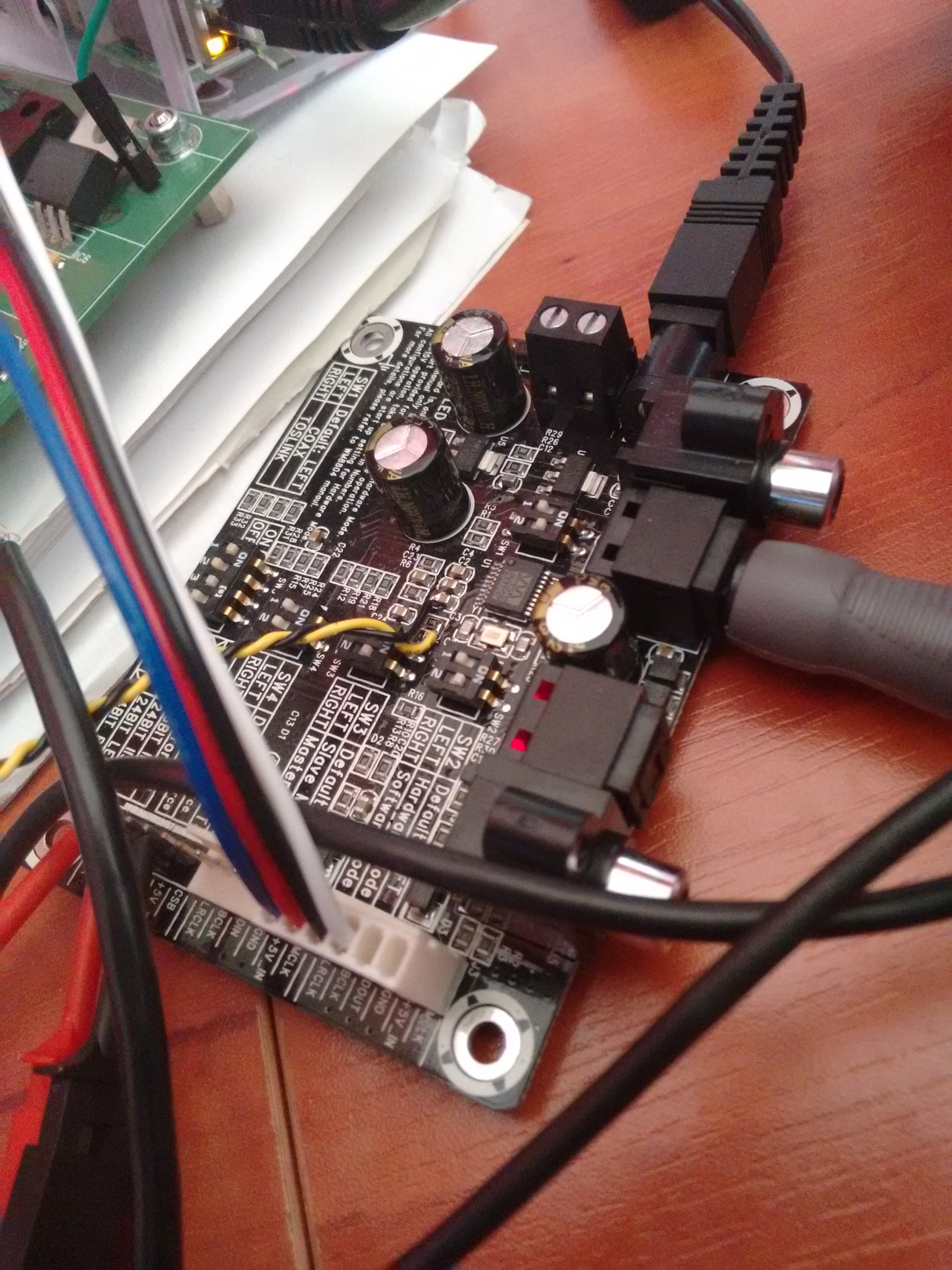
Balls to the wall
 So let’s pit this thing against an opamp stage and see what happens. In the left corner, representing the heavyweight class, the Analog Devices OPA275. The challenging contestant, some ridiculous discrete design from some dude in 2003 thinking they know better. All that and more, in part 2…